Schmersal 101170036
Estimated Delivery between and with free shipping.
Overnight shipping is also available.
 Free Shipping
 1 Year Warranty
 A+ Rated On The BBB
 10% Off First Order
 Based In The USA
Description
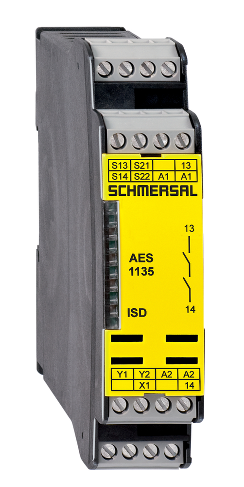
AES 1135
Schmersal 101170036 is now available from Williams Automation.
If you need a specific firmware version or series for this item, please call or email us with your request. We can also provide specifications and/or a data sheet for this item upon request. Please call or email us if you need one.
We offer Overnight shipping for most items listed on our website. Please get in touch with us to confirm whether the product can ship overnight on the day of your order. Cutoff times are typically 2-3 PM EST. Lead times can range from 1 to 4 business days.
Call (803) 761-7027 if you have any questions about availability, or email us at sales@williamsautomation.com.
Ambient conditions
- Ambient temperature
- +0 ... +55 °C
- Degree of protection of clips or terminals
- IP20
- Degree of protection of the enclosure
- IP40
- Degree of protection of the mounting space
- IP54
- Resistance to vibrations
- 10...55 Hz, Amplitude 0.35 mm, ± 15 %
- Restistance to shock
- 30 g / 11 ms
- Storage and transport temperature, maximum
- +70 °C
- Storage and transport temperature, minimum
- -25 °C
Ambient conditions - Insulation values
- Degree of pollution
- 2
- Overvoltage category
- III
- Rated impulse withstand voltage U
- 4 kV
Approvals - Standards
- Certificates
- BG | cULus
Electrical data
- Contact resistance, maximum
- 0.1 Ω
- Drop-out delay in case of emergency, typically
- 20 ms
- Drop-out delay in case of power failure, typically
- 80 ms
- Electrical power consumption
- 5 W
- Frequency range
- 50 Hz | 60 Hz
- Material of the contacts, electrical
- Ag-Ni 10 and 0.2 µm gold-plated
- Note (Contact resistance)
- in new state
- Operating voltage
- 24 VAC -15 % / +10 % | 24 VDC -10 % / +20 %
- Pull-in delay at automatic start, maximum, typically
- 100 ms
- Pull-in delay at RESET, typically
- 20 ms
- Rated AC voltage for controls, 50 Hz, minimum
- 20.4 VAC
- Rated AC voltage for controls, 60 Hz, minimum
- 20.4 VAC
- Rated AC voltage for controls at DC minimum
- 20.4 VDC
- Rated control voltage at AC 50 Hz, maximum
- 26.4 VAC
- Rated control voltage at AC 60 Hz, maximum
- 26.4 VAC
- Rated control voltage at DC, maximum
- 28.8 VDC
- Rated operating voltage
- 24 VDC
- 24 VAC
- Ripple voltage
- 10 %
- Thermal test current
- 6 A
Electrical data - Digital inputs
- Conduction resistance, maximum
- 40 Ω
- Input signal, HIGH Signal "1"
- 10 … 30 VDC
- Input signal, LOW Signal "0"
- 0 … 2 VDC
Electrical data - Digital Output
- Current, Utilisation category DC-12
- 0.1 A
- Voltage, Utilisation category DC-12
- 24 VDC
Electrical data - Electromagnetic compatibility (EMC)
- EMC rating
- EMC-Directive
Electrical data - Relay outputs (auxiliary contacts)
- Switching capacity, maximum
- 2 A
- 24 VDC
Electrical data - Safe relay outputs
- Current, Utilisation category AC-15
- 6 A
- Current, Utilisation category DC-13
- 6 A
- Switching capacity, maximum
- 250 VAC
- 8 A
- Switching capacity, minimum
- 10 VDC
- 10 mA
- Voltage, Utilisation category AC-15
- 230 VAC
- Voltage, Utilisation category DC-13
- 24 VDC
General data
- Climatic stress
- EN 60068-2-3 | BG-GS-ET-14
- Enclosure material
- Glass-fibre reinforced thermoplastic, ventilated
- Gross weight
- 155 g
- Standards
- BG-GS-ET-14 | BG-GS-ET-20 | EN IEC 62061 | EN ISO 13849-1 | EN IEC 60947-5-1 | EN IEC 60947-5-3 | EN IEC 60947-5-5 | EN IEC 60204-1 | EN IEC 60947-1
General data - Features
- Automatic reset function
- Yes
- Cross-circuit detection
- Yes
- Earth connection detection
- Yes
- Integral system diagnostics, status
- Yes
- Number of LEDs
- 1
- Number of normally closed (NC)
- 2
- Number of normally open (NO)
- 1
- Number of safety contacts
- 1
- Number of signalling outputs
- 2
- Number of undelayed semi-conductor outputs with signaling function
- 2
- Reset after disconnection of supply voltage
- Yes
- Stop-Category
- 0
- Wire breakage detection
- Yes
Integral system diagnosis (ISD)
- Faults
- Failure of the safety relay to pull-in or drop-out | Failure of door contacts to open or close | Cross-wire or short-circuit monitoring of the switch connections | Interruption of the switch connections | Fault on the input circuits or the relay control circuits of the safety monitoring module
- Note (ISD -Faults)
- The following faults are registered by the safety monitoring modules and indicated by ISD.
Mechanical data
- Mechanical life, minimum
- 20,000,000 Operations
- Mounting
- Snaps onto standard DIN rail to EN 60715
Mechanical data - Connection technique
- Cable section, maximum
- 2.5 mm²
- Cable section, minimum
- 0.25 mm²
- Terminal designations
- IEC/EN 60947-1
- Termination
- rigid or flexible | Screw terminals M20 x 1.5
- Tightening torque of Clips
- 0.6 Nm
Mechanical data - Dimensions
- Depth
- 121 mm
- Height
- 100 mm
- Width
- 22.5 mm
Note
- Note (General)
- Inductive loads (e.g. contactors, relays, etc.) are to be suppressed by means of a suitable circuit.
Other data
- Note (applications)
- Safety sensor | Guard system
Safety classification
- Category
- 3
- Mission time
- 20 Year(s)
- Performance Level, up to
- d
- PFH value
- 1.00 x 10⁻⁷ /h
- Safety Integrity Level (SIL), suitable for applications in
- 2
- Standards
- EN ISO 13849-1 | EN IEC 61508
Specifications
- Depth
- 121 mm
- Height
- 100 mm
- Width
- 22.5 mm
Wiring example
- Note (Wiring diagram)
- The wiring diagram is shown with guard doors closed and in de-energised condition. | To secure a guard door up to PL d and Category 3 | Monitoring 1 guard door(s), each with a magnetic safety sensor of the BNS range | If one or two external relays or contactors are used to switch the load, the system can then only be classified in Category 3 to EN ISO 13849-1, if exclusion of the fault “Failure of the external contactors” can be substantiated and is documented, e.g. by using reliable down-rated contactors. A second contactor leads to an increase in the level of security by redundant switching to switch the load off. | Modification for 2 NC contacts: The safety monitoring module can be modified to monitor two NC contacts by bridging the terminals A1 and X1. In this configuration, the short-circuit detection becomes inoperative. | Expansion of enable delay time: The enable delay time can be increased from 0.1 s to 1.0 s by changing the position of a jumper link connection under the cover of the unit. | The ISD tables (Intergral System Diagnostics) for analysis of the fault indications and their causes are shown in the appendix.
Reviews
What our customers say
they have quick great service and quick shipping!! would recommend doing business over and over!!
January 7 on 
Great price and speedy delivery. I am certain, based on my first statement that if needed, customer support will be excellent
December 31 on
Great customer service, fast shipping. Nice to deal with a company that shows they care about their customers.
December 5 on
I got the part and it was exactly what i needed to get my dust collector up and running again! It was also at very reasonable price. Thanks!
December 4 on
Another great purchase from Williams Automation. You will have peace of mind knowing your getting authentic parts from Williams Automation. Very easy to work with and great customer service. Plus you get at a competitive price and not three times what it should be.
November 6 on
Exceptional customer service! They had the elusive part I required readily available and responded promptly to all my emails.
November 2 on
Great customer service. Had the hard to find parts I needed in stock. All emails answered promptly.
October 9 on
Had what I needed in stock, shipped fast and arrived within the time frame indicated. It was packaged securely.
August 28 on
Perfect purchase! The whole process was great, including the packaging and shipping. Finally a company who cares!
August 13 on
Great service and Best prices ! Very organized company and helpful too. Will definitely buy again
August 10 on