
Phoenix Contact 2702132
 Free Shipping
 1 Year Warranty
 A+ Rated On The BBB
 10% Off First Order
 Based In The USA
Description
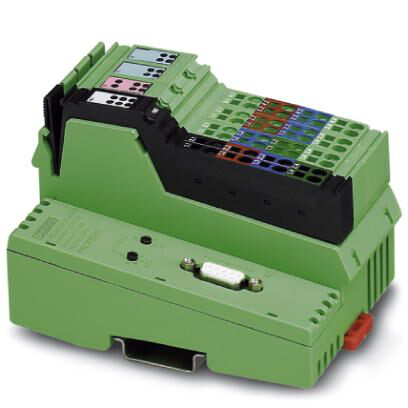
Inline XC, Bus coupler, PROFIBUS DP, D-SUB-9 female connector, Digital inputs: 8, 24 V DC, connection method: 3-wire, Digital outputs: 4, 24 V DC, 500 mA, connection method: 3-wire, Extreme conditions version, transmission speed in the local bus: 500 kbps / 2 Mbps, degree of protection: IP20, including Inline connectors and marking fieldsBus coupler - IL PB BK DI8 DO4/EF-XC-PAC - 2702132
Phoenix Contact 2702132 is now available from Williams Automation.
If you need a specific firmware version or series for this item, please call or email us with your request. We can also provide specifications and/or a data sheet for this item upon request. Please call or email us if you need one.
We offer Overnight shipping for most items listed on our website. Please get in touch with us to confirm whether the product can ship overnight on the day of your order. Cutoff times are typically 2-3 PM EST. Lead times can range from 1 to 4 business days.
Call (803) 761-7027 if you have any questions about availability, or email us at sales@williamsautomation.com.
Ambient conditions
- Air pressure (operation)
- 70 kPa - 106 kPa (up to 3000 m above sea level)
- Air pressure (storage/transport)
- 70 kPa - 106 kPa (up to 3000 m above sea level)
- Ambient temperature (operation)
- -25 °C - 55 °C
- -40 °C - 70 °C (Extended, see section 'Tested successfully: use under extreme ambient conditions' in the data sheet.)
- Ambient temperature (storage/transport)
- -40 °C - 85 °C
- Degree of protection
- IP20
- Permissible humidity (operation)
- 10 % - 95 % (non-condensing)
- Permissible humidity (storage/transport)
- 10 % - 95 % (according to DIN EN 61131-2)
Connection data
- Conductor cross section AWG max.
- 16
- Conductor cross section AWG min.
- 28
- Conductor cross section flexible max.
- 1.5 mm²
- Conductor cross section flexible min.
- 0.08 mm²
- Conductor cross section solid max.
- 1.5 mm²
- Conductor cross section solid min.
- 0.08 mm²
- Connection method
- Spring-cage connection
- Designation
- Inline connector
- Stripping length
- 8 mm
Digital inputs
- Connection method
- Inline connector
- Connection technology
- 3-wire
- Delay at signal change from 0 to 1
- 2.9 ms
- Delay at signal change from 1 to 0
- 2.9 ms
- Description of the input
- EN 61131-2 type 1
- Input name
- Digital inputs
- Input voltage
- 24 V DC
- Input voltage range "0" signal
- -30 V DC - 5 V DC
- Input voltage range "1" signal
- 15 V DC - 30 V DC
- Nominal input current at UIN
- typ. 3 mA
- Nominal input voltage UIN
- 24 V DC
- Number of inputs
- 8
- Protective circuit
- Reverse polarity protection Suppressor diode
- Typical input current per channel
- typ. 3 mA
- Typical response time
- approx. 500 µs
Digital outputs
- Behavior with inductive overload
- Output can be destroyed
- Behavior with overload
- Auto restart
- Connection method
- Inline connector
- Connection technology
- 3-wire
- Limitation of the voltage induced on circuit interruption
- approx. -30 V
- Maximum output current per channel
- 500 mA
- Maximum output current per module
- 2 A
- Maximum output current per module / terminal block
- 2 A
- Nominal load, inductive
- 12 VA (1.2 H, 48 Ω)
- Nominal load, lamp
- 12 W
- Nominal load, ohmic
- 12 W
- Nominal output voltage
- 24 V DC
- Number of outputs
- 4
- Output current when switched off
- max. 10 µA (When not loaded, a voltage can be measured even at an output that is not set.)
- Output name
- Digital outputs
- Output voltage
- 24 V DC -1 V (At nominal current)
- Protective circuit
- Short-circuit and overload protection Freewheeling circuit in the output driver
- Reverse voltage resistance to short pulses
- Reverse voltage proof
Dimensions
- Depth
- 71.5 mm
- Height
- 119.8 mm
- Note on dimensions
- Specfications with connectors
- Width
- 80 mm
Environmental Product Compliance
- China RoHS
- No hazardous substances above threshold values
- Environmentally friendly use period: unlimited = EFUP-e
- REACh SVHC
- Lead 7439-92-1
Inline potentials
- Current consumption
- max. 0.98 A
- 80 mA (without connected I/O terminal blocks)
- 6 mA (without connected peripherals)
- max. 8 A DC
- Designation
- Bus coupler supply UBC; Communications power UL (7.5 V) and the analog supply UANA (24 V) are generated from the bus coupler supply.
- Segment circuit supply (US)
- Main circuit supply (UM)
- Supply of analog modules (UANA)
- Communications power (UL)
- Power consumption
- typ. 1.7 W (entire device)
- Power supply unit
- max. 8 A DC (sum of UM + US)
- max. 0.8 A DC
- max. 0.5 A DC
- Supply voltage
- 24 V DC (via Inline connector)
- 24 V DC
- 7.5 V DC
- Supply voltage range
- 19.2 V DC - 30 V DC (including all tolerances, including ripple)
Standards and Regulations
- Connection in acc. with standard
- CUL
- Mechanical tests
- Vibration resistance in acc. with EN 60068-2-6/IEC 60068-2-6 5g
- Shock in acc. with EN 60068-2-27/IEC 60068-2-27 Operation: 25g, 11 ms duration, semi-sinusoidal shock impulse
- Protection class
- III (IEC 61140, EN 61140, VDE 0140-1)
System limits of the bus coupler
- Amount of process data
- max. 244 Byte (Output)
- max. 488 Byte (per station)
- max. 244 Byte (Input)
- Designation
- System limits of the bus coupler
- Number of configuration data
- max. 244 Byte (including 5 bytes for the local inputs and outputs)
- Number of devices with parameter channel
- max. 16
- Number of local bus devices that can be connected
- max. 61 (The on-board I/Os are two devices)
- Number of parameter data
- max. 244 Byte (including 14 bytes for the bus coupler, DP/V1, and the local inputs and outputs)
- Number of supported branch terminals with remote bus branch
- 0
- Number of supported devices
- max. 63 (per station)
- Response time of I/Os
- typ. 4 ms (aligned I/Os; transmission speed: PROFIBUS 1.5 Mbps, local bus 500 kbps)
Reviews
What our customers say
 BBB 4.7
  Rating
 they have quick great service and quick shipping!! would recommend doing business over and over!!
January 7 on 

Great price and speedy delivery. I am certain, based on my first statement that if needed, customer support will be excellent
December 31 on
Great customer service, fast shipping. Nice to deal with a company that shows they care about their customers.
December 5 on
I got the part and it was exactly what i needed to get my dust collector up and running again! It was also at very reasonable price. Thanks!
December 4 on
Another great purchase from Williams Automation. You will have peace of mind knowing your getting authentic parts from Williams Automation. Very easy to work with and great customer service. Plus you get at a competitive price and not three times what it should be.
November 6 on
Exceptional customer service! They had the elusive part I required readily available and responded promptly to all my emails.
November 2 on
Great customer service. Had the hard to find parts I needed in stock. All emails answered promptly.
October 9 on
Had what I needed in stock, shipped fast and arrived within the time frame indicated. It was packaged securely.
August 28 on
Perfect purchase! The whole process was great, including the packaging and shipping. Finally a company who cares!
August 13 on
Great service and Best prices ! Very organized company and helpful too. Will definitely buy again
August 10 on