ABB AF09-30-10-41
Estimated Delivery between and with free shipping.
Overnight shipping is also available.
 Free Shipping
 1 Year Warranty
 A+ Rated On The BBB
 10% Off First Order
 Based In The USA
Description
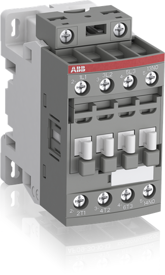
The AF09-30-10-41 is a 3 pole - 690 V IEC or 600 UL contactor with 1 built-in auxiliary contact and screw terminals, controlling motors up to 4 kW / 400 V AC (AC-3) or 5 hp / 480 V UL and switching power circuits up to 25 A (AC-1) or 25 A UL general use. Thanks to the AF technology, the contactor has a wide control voltage range (24-60 V 50/60 Hz), managing large control voltage variations, reducing panel energy consumptions and ensuring distinct operations in unstable networks. Furthermore, surge protection is built-in, offering a compact solution. AF contactors have a block type design, can be easily extended with add-on auxiliary contact blocks and an additional wide range of accessories.AF09-30-10-41 24-60V50/60HZ Contactor
ABB AF09-30-10-41 is now available from Williams Automation.
If you need a specific firmware version or series for this item, please call or email us with your request. We can also provide specifications and/or a data sheet for this item upon request. Please call or email us if you need one.
We offer Overnight shipping for most items listed on our website. Please get in touch with us to confirm whether the product can ship overnight on the day of your order. Cutoff times are typically 2-3 PM EST. Lead times can range from 1 to 4 business days.
Call (803) 761-7027 if you have any questions about availability, or email us at sales@williamsautomation.com.
Classifications
- eClass
- V11.0 : 27371003
- ETIM 4
- EC000066 - Magnet contactor, AC-switching
- ETIM 5
- EC000066 - Magnet contactor, AC-switching
- IDEA Granular Category Code (IGCC)
- 4758 >> Iec Contactors
- Object Classification Code
- Q
Dimensions
- Product Net Depth / Length
- 77 mm
- Product Net Height
- 86 mm
- Product Net Weight
- 0.27 kg
- Product Net Width
- 45 mm
Environmental
- Ambient Air Temperature
- Close to Contactor Fitted with Thermal O/L Relay -25 ... 60 °CClose to Contactor without Thermal O/L Relay -40 ... 70 °CClose to Contactor for Storage -60 ... +80 °C
- Climatic Withstand
- Category B according to IEC 60947-1 Annex Q
- Maximum Operating Altitude Permissible
- Without Derating 3000 m
- Resistance to Shock acc. to IEC 60068-2-27
- Closed, Shock Direction: B1 25 gOpen, Shock Direction: B1 5 gShock Direction: A 30 gShock Direction: B2 15 gShock Direction: C1 25 gShock Direction: C2 25 g
- Resistance to Vibrations acc. to IEC 60068-2-6
- 5 ... 300 Hz 4 g closed position / 2 g open position
- RoHS Status
- Following EU Directive 2011/65/EU
Ordering
- Customs Tariff Number
- 85364900
- Minimum Order Quantity
- 1 piece
Technical
- Connecting Capacity Auxiliary Circuit
- Flexible with Ferrule 1/2x 0.75 ... 2.5 mm²Flexible with Insulated Ferrule 2x 0.75 ... 1.5 mm²Flexible with Insulated Ferrule 1x 0.75 ... 2.5 mm²Rigid Solid 1/2x 1 ... 2.5 mm²Rigid Stranded 1/2x 1 ... 2.5 mm²
- Connecting Capacity Control Circuit
- Flexible with Ferrule 1/2x 0.75 ... 2.5 mm²Flexible with Insulated Ferrule 1x 0.75 ... 2.5 mm²Flexible with Insulated Ferrule 2x 0.75 ... 1.5 mm²Rigid Solid 1/2x 1 ... 2.5 mm²Rigid Stranded 1/2x 1 ... 2.5 mm²
- Connecting Capacity Main Circuit
- Flexible with Ferrule 1/2x 0.75 ... 6 mm²Flexible with Insulated Ferrule 1x 0.75 ... 4 mm²Flexible with Insulated Ferrule 2x 0.75 ... 2.5 mm²Rigid Solid 1/2x 1 ... 4 mm²Rigid Stranded 1/2x 1 ... 6 mm²
- Conventional Free-air Thermal Current (Ith)
- acc. to IEC 60947-4-1, Open Contactors Θ = 40 °C 35 Aacc. to IEC 60947-5-1, Θ = 40 °C 16 A
- Degree of Protection
- acc. to IEC 60529, IEC 60947-1, EN 60529 Auxiliary Terminals IP20acc. to IEC 60529, IEC 60947-1, EN 60529 Coil Terminals IP20acc. to IEC 60529, IEC 60947-1, EN 60529 Main Terminals IP20
- Maximum Breaking Capacity
- cos phi=0.45 (cos phi=0.35 for Ie > 100 A) at 440 V 250 Acos phi=0.45 (cos phi=0.35 for Ie > 100 A) at 690 V 106 A
- Maximum Electrical Switching Frequency
- (AC-1) 600 cycles per hour(AC-15) 1200 cycles per hour(AC-2 / AC-4) 300 cycles per hour(AC-3) 1200 cycles per hour(DC-13) 900 cycles per hour
- Maximum Mechanical Switching Frequency
- 3600 cycles per hour
- Mounting by Screws (not supplied)
- 2 x M4 screws placed diagonally
- Mounting on DIN Rail
- TH35-15 (35 x 15 mm Mounting Rail) acc. to IEC 60715TH35-7.5 (35 x 7.5 mm Mounting Rail) acc. to IEC 60715
- Number of Auxiliary Contacts NC
- 0
- Number of Auxiliary Contacts NO
- 1
- Number of Main Contacts NC
- 0
- Number of Main Contacts NO
- 3
- Operate Time
- Between Coil De-energization and NC Contact Closing 13 ... 98 msBetween Coil De-energization and NO Contact Opening 11 ... 95 msBetween Coil Energization and NC Contact Opening 38 ... 90 msBetween Coil Energization and NO Contact Closing 40 ... 95 ms
- Rated Control Circuit Voltage (Uc)
- 50 Hz 24 ... 60 V60 Hz 24 ... 60 VDC Operation -
- Rated Frequency (f)
- Auxiliary Circuit 50 / 60 HzControl Circuit 50 / 60 HzMain Circuit 50 / 60 Hz
- Rated Impulse Withstand Voltage (Uimp)
- 6 kV
- Rated Insulation Voltage (Ui)
- acc. to IEC 60947-4-1 690 Vacc. to IEC 60947-5-1 690 Vacc. to UL/CSA 600 V
- Rated Operational Current AC-15 (Ie)
- (500 V) 2 A(690 V) 2 A(24 / 127 V) 6 A(220 / 240 V) 4 A(400 / 440 V) 3 A
- Rated Operational Current AC-1 (Ie)
- (690 V) 40 °C 25 A(690 V) 60 °C 25 A(690 V) 70 °C 22 A
- Rated Operational Current AC-3e (Ie)
- (415 V) 60 °C 9 A(440 V) 60 °C 9 A(500 V) 60 °C 9.5 A(690 V) 60 °C 7 A(380 / 400 V) 60 °C 9 A(220 / 230 / 240 V) 60 °C 9 A
- Rated Operational Current AC-3 (Ie)
- (415 V) 60 °C 9 A(440 V) 60 °C 9 A(500 V) 60 °C 9.5 A(690 V) 60 °C 7 A(380 / 400 V) 60 °C 9 A(220 / 230 / 240 V) 60 °C 9 A
- Rated Operational Current DC-13 (Ie)
- (24 V) 6 A / 144 W(48 V) 2.8 A / 134 W(72 V) 1 A / 72 W(110 V) 0.55 A / 60 W(125 V) 0.55 A / 69 W(220 V) 0.27 A / 60 W(250 V) 0.27 A / 68 W(400 V) 0.15 A / 60 W(500 V) 0.13 A / 65 W(600 V) 0.1 A / 60 W
- Rated Operational Current DC-1 (Ie)
- (110 V) 1-Pole, 40 °C 10 A(110 V) 1-Pole, 60 °C 10 A(110 V) 1-Pole, 70 °C 10 A(110 V) 2 Poles in Series, 40 °C 25 A(110 V) 2 Poles in Series, 60 °C 25 A(110 V) 2 Poles in Series, 70 °C 22 A(110 V) 3 Poles in Series, 40 °C 25 A(110 V) 3 Poles in Series, 60 °C 25 A(110 V) 3 Poles in Series, 70 °C 22 A(220 V) 2 Poles in Series, 40 °C 10 A(220 V) 2 Poles in Series, 60 °C 10 A(220 V) 2 Poles in Series, 70 °C 10 A(220 V) 3 Poles in Series, 40 °C 25 A(220 V) 3 Poles in Series, 60 °C 25 A(220 V) 3 Poles in Series, 70 °C 22 A(72 V) 1-Pole, 40 °C 25 A(72 V) 1-Pole, 60 °C 25 A(72 V) 1-Pole, 70 °C 22 A(72 V) 2 Poles in Series, 40 °C 25 A(72 V) 2 Poles in Series, 60 °C 25 A(72 V) 2 Poles in Series, 70 °C 22 A(72 V) 3 Poles in Series, 40 °C 25 A(72 V) 3 Poles in Series, 60 °C 25 A(72 V) 3 Poles in Series, 70 °C 22 A
- Rated Operational Current DC-3 (Ie)
- (110 V) 1-Pole, 40 °C 6 A(110 V) 1-Pole, 60 °C 6 A(110 V) 1-Pole, 70 °C 6 A(110 V) 2 Poles in Series, 40 °C 25 A(110 V) 2 Poles in Series, 60 °C 25 A(110 V) 2 Poles in Series, 70 °C 22 A(110 V) 3 Poles in Series, 40 °C 25 A(110 V) 3 Poles in Series, 60 °C 25 A(110 V) 3 Poles in Series, 70 °C 22 A(220 V) 2 Poles in Series, 40 °C 6 A(220 V) 2 Poles in Series, 60 °C 6 A(220 V) 2 Poles in Series, 70 °C 6 A(220 V) 3 Poles in Series, 40 °C 25 A(220 V) 3 Poles in Series, 60 °C 25 A(220 V) 3 Poles in Series, 70 °C 22 A(72 V) 1-Pole, 40 °C 25 A(72 V) 1-Pole, 60 °C 25 A(72 V) 1-Pole, 70 °C 22 A(72 V) 2 Poles in Series, 40 °C 25 A(72 V) 2 Poles in Series, 60 °C 25 A(72 V) 2 Poles in Series, 70 °C 22 A(72 V) 3 Poles in Series, 40 °C 25 A(72 V) 3 Poles in Series, 60 °C 25 A(72 V) 3 Poles in Series, 70 °C 22 A
- Rated Operational Current DC-5 (Ie)
- (110 V) 1-Pole, 40 °C 4 A(110 V) 1-Pole, 60 °C 4 A(110 V) 1-Pole, 70 °C 4 A(110 V) 2 Poles in Series, 40 °C 10 A(110 V) 2 Poles in Series, 60 °C 10 A(110 V) 2 Poles in Series, 70 °C 10 A(110 V) 3 Poles in Series, 40 °C 25 A(110 V) 3 Poles in Series, 60 °C 25 A(110 V) 3 Poles in Series, 70 °C 22 A(220 V) 2 Poles in Series, 40 °C 4 A(220 V) 2 Poles in Series, 60 °C 4 A(220 V) 2 Poles in Series, 70 °C 4 A(220 V) 3 Poles in Series, 40 °C 9 A(220 V) 3 Poles in Series, 60 °C 9 A(220 V) 3 Poles in Series, 70 °C 9 A(72 V) 1-Pole, 40 °C 9 A(72 V) 1-Pole, 60 °C 9 A(72 V) 1-Pole, 70 °C 9 A(72 V) 2 Poles in Series, 40 °C 25 A(72 V) 2 Poles in Series, 60 °C 25 A(72 V) 2 Poles in Series, 70 °C 22 A(72 V) 3 Poles in Series, 40 °C 25 A(72 V) 3 Poles in Series, 60 °C 25 A(72 V) 3 Poles in Series, 70 °C 22 A
- Rated Operational Power AC-3e (Pe)
- (415 V) 4 kW(440 V) 4 kW(500 V) 5.5 kW(690 V) 5.5 kW(380 / 400 V) 4 kW(220 / 230 / 240 V) 2.2 kW
- Rated Operational Power AC-3 (Pe)
- (400 V) 4 kW(415 V) 4 kW(440 V) 4 kW(500 V) 5.5 kW(690 V) 5.5 kW(380 / 400 V) 4 kW(220 / 230 / 240 V) 2.2 kW
- Rated Operational Voltage
- Auxiliary Circuit 690 VMain Circuit 690 V
- Rated Short-time Withstand Current Low Voltage (Icw)
- at 40 °C Ambient Temp, in Free Air, from a Cold State 10 s 150 Aat 40 °C Ambient Temp, in Free Air, from a Cold State 15 min 35 Aat 40 °C Ambient Temp, in Free Air, from a Cold State 1 min 60 Aat 40 °C Ambient Temp, in Free Air, from a Cold State 1 s 300 Aat 40 °C Ambient Temp, in Free Air, from a Cold State 30 s 80 Afor 0.1 s 140 Afor 1 s 100 A
- Standards
- IEC 60947-1 / 60947-4-1 and EN 60947-1 / 60947-4-16, UL 60947-4-1, CSA C22.2 No. 60947-4-1
- Terminal Type
- Screw Terminals
- Wire Stripping Length
- Auxiliary Circuit 10 mmControl Circuit 10 mmMain Circuit 10 mm
Technical UL/CSA
- Connecting Capacity Auxiliary Circuit UL/CSA
- Rigid Solid 1/2x 18-14 AWGRigid Stranded 1/2x 18-14 AWG
- Connecting Capacity Control Circuit UL/CSA
- Rigid Solid 1/2x 18-14 AWGRigid Stranded 1/2x 18-14 AWG
- Connecting Capacity Main Circuit UL/CSA
- Rigid Solid 1/2x 16-10 AWGRigid Stranded 1/2x 16-10 AWG
- Continuous Current Rating NEMA
- 9 A
- General Use Rating UL/CSA
- (600 V AC) 25 A
- Horsepower Rating NEMA
- (115 V AC) Single Phase 1/3 Hp(200 V AC) Three Phase 1-1/2 Hp(230 V AC) Single Phase 1 Hp(230 V AC) Three Phase 1-1/2 Hp(460 V AC) Three Phase 2 Hp(575 V AC) Three Phase 2 Hp
- Horsepower Rating UL/CSA
- (120 V AC) Single Phase 3/4 hp(200 ... 208 V AC) Three Phase 2 hp(220 ... 240 V AC) Three Phase 2 hp(240 V AC) Single Phase 1-1/2 hp(440 ... 480 V AC) Three Phase 5 hp(550 ... 600 V AC) Three Phase 7-1/2 hp
- NEMA Size
- 00
- Tightening Torque UL/CSA
- Auxiliary Circuit 11 in·lbControl Circuit 11 in·lbMain Circuit 13 in·lb
Reviews
What our customers say
they have quick great service and quick shipping!! would recommend doing business over and over!!
January 7 on 
Great price and speedy delivery. I am certain, based on my first statement that if needed, customer support will be excellent
December 31 on
Great customer service, fast shipping. Nice to deal with a company that shows they care about their customers.
December 5 on
I got the part and it was exactly what i needed to get my dust collector up and running again! It was also at very reasonable price. Thanks!
December 4 on
Another great purchase from Williams Automation. You will have peace of mind knowing your getting authentic parts from Williams Automation. Very easy to work with and great customer service. Plus you get at a competitive price and not three times what it should be.
November 6 on
Exceptional customer service! They had the elusive part I required readily available and responded promptly to all my emails.
November 2 on
Great customer service. Had the hard to find parts I needed in stock. All emails answered promptly.
October 9 on
Had what I needed in stock, shipped fast and arrived within the time frame indicated. It was packaged securely.
August 28 on
Perfect purchase! The whole process was great, including the packaging and shipping. Finally a company who cares!
August 13 on
Great service and Best prices ! Very organized company and helpful too. Will definitely buy again
August 10 on