ABB A210-30-11-84
Estimated Delivery between and with free shipping.
Overnight shipping is also available.
 Free Shipping
 1 Year Warranty
 A+ Rated On The BBB
 10% Off First Order
 Based In The USA
Description
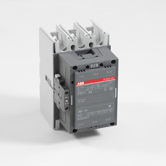
A 3-phase Contactor suitable for various applications such as Motor starting, Isolation, By-pass and Distribution application up to max 690 V.Operated with control voltage, versions from 24….690 AC, 50 and 60 HzA210-30-11 110V 50Hz / 110-120V 60Hz Contactor
ABB A210-30-11-84 is now available from Williams Automation.
If you need a specific firmware version or series for this item, please call or email us with your request. We can also provide specifications and/or a data sheet for this item upon request. Please call or email us if you need one.
We offer Overnight shipping for most items listed on our website. Please get in touch with us to confirm whether the product can ship overnight on the day of your order. Cutoff times are typically 2-3 PM EST. Lead times can range from 1 to 4 business days.
Call (803) 761-7027 if you have any questions about availability, or email us at sales@williamsautomation.com.
Classifications
- eClass
- V11.0 : 27371003
- E-Number (Norway)
- 4115174
- E-Number (Sweden)
- 3227873
- ETIM 4
- EC000066 - Magnet contactor, AC-switching
- ETIM 5
- EC000066 - Magnet contactor, AC-switching
- IDEA Granular Category Code (IGCC)
- 4755 >> Contactors
- Object Classification Code
- Q
Dimensions
- Product Net Depth / Length
- 180.5 mm
- Product Net Height
- 227 mm
- Product Net Weight
- 5.4 kg
- Product Net Width
- 140 mm
Environmental
- Ambient Air Temperature
- Close to Contactor Fitted with Thermal O/L Relay (0.85 ... 1.1 Uc) -25 ... 50 °CClose to Contactor without Thermal O/L Relay (0.85 ... 1.1 Uc) -40 ... 70 °CClose to Contactor for Storage -40 ... 70 °C
- Maximum Operating Altitude Permissible
- Without Derating 3000 m
- Resistance to Shock acc. to IEC 60068-2-27
- Shock Direction: A 5 gShock Direction: B1 5 gShock Direction: B2 5 gShock Direction: C1 5 gShock Direction: C2 5 g
- RoHS Status
- Following EU Directive 2011/65/EU
Ordering
- Customs Tariff Number
- 85364900
- Minimum Order Quantity
- 1 piece
- Replacement Product ID (NEW)
- 1SFL527002R1311
Technical
- Coil Consumption
- Holding at Max. Rated Control Circuit Voltage 50 Hz 60 V·AHolding at Max. Rated Control Circuit Voltage 60 Hz 65 V·APull-in at Max. Rated Control Circuit Voltage 50 Hz 1350 V·APull-in at Max. Rated Control Circuit Voltage 60 Hz 1550 V·A
- Coil Operating Limits
- (acc. to IEC 60947-4-1) 0.85 x Uc Min. ... 1.1 x Uc Max. (at θ ≤ 70 °C)
- Connecting Capacity Auxiliary Circuit
- Flexible with Ferrule 1x 0.75 ... 2.5 mm²Flexible with Insulated Ferrule 2x 0.75 ... 2.5 mm²Flexible 2x0.75 ... 2.5 mm²Solid 2 x 1 ... 4 mm²Stranded 1 x 1 .... 4 mm²
- Connecting Capacity Main Circuit
- Bar 32 mm²Rigid Al-Cable 120 ... 240 mm²Rigid Cu-Cable 16 ... 240 mm²
- Connecting Terminals (delivered in open position) Main Poles
- Flat type c/w screws and bolts
- Conventional Free-air Thermal Current (Ith)
- acc. to IEC 60947-4-1, Open Contactors Θ = 40 °C 350 A
- Degree of Protection
- acc. to IEC 60529, IEC 60947-1, EN 60529 Coil Terminals IP20acc. to IEC 60529, IEC 60947-1, EN 60529 Main Terminals IP00
- Maximum Breaking Capacity
- cos phi=0.45 (cos phi=0.35 for Ie > 100 A) at 440 V 2200 Acos phi=0.45 (cos phi=0.35 for Ie > 100 A) at 690 V 2000 A
- Maximum Electrical Switching Frequency
- (AC-1) 300 cycles per hour(AC-2 / AC-4) 150 cycles per hour(AC-3) 300 cycles per hour
- Maximum Mechanical Switching Frequency
- 3600 cycles per hour
- Mechanical Durability
- 5 million
- Number of Auxiliary Contacts NC
- 1
- Number of Auxiliary Contacts NO
- 1
- Number of Main Contacts NC
- 0
- Number of Main Contacts NO
- 3
- Operate Time
- Between Coil De-energization and NC Contact Closing 7 ... 13 msBetween Coil De-energization and NO Contact Opening 10 ... 16 msBetween Coil Energization and NC Contact Opening 12 ... 30 msBetween Coil Energization and NO Contact Closing 17 ... 35 ms
- Rated Breaking Capacity AC-3
- 8 x Ie AC-3
- Rated Control Circuit Voltage (Uc)
- 50 Hz 110 V60 Hz 110 ... 120 V
- Rated Frequency (f)
- Main Circuit 50 / 60 Hz
- Rated Impulse Withstand Voltage (Uimp)
- Main Circuit 8 kV
- Rated Insulation Voltage (Ui)
- acc. to IEC 60947-4-1 and VDE 0110 (Gr. C) 1000 Vacc. to UL/CSA 600 V
- Rated Making Capacity AC-3
- 10 x Ie AC-3
- Rated Operational Current AC-1 (Ie)
- (690 V) 40 °C 350 A(690 V) 55 °C 300 A(690 V) 70 °C 240 A
- Rated Operational Current AC-3 (Ie)
- (415 V) 55 °C 210 A(440 V) 55 °C 210 A(500 V) 55 °C 210 A(690 V) 55 °C 210 A(380 / 400 V) 55 °C 210 A(220 / 230 / 240 V) 55 °C 210
- Rated Operational Current DC-1 (Ie)
- (110 V) 2 Poles in Series, 40 °C 350 A(220 V) 3 Poles in Series, 40 °C 350 A
- Rated Operational Current DC-3 (Ie)
- (110 V) 2 Poles in Series, 40 °C 350 A(220 V) 3 Poles in Series, 40 °C 350 A
- Rated Operational Current DC-5 (Ie)
- (110 V) 2 Poles in Series, 40 °C 350 A(220 V) 3 Poles in Series, 40 °C 350 A
- Rated Operational Power AC-3 (Pe)
- (415 V) 110 kW(440 V) 110 kW(500 V) 132 kW(690 V) 160 kW(380 / 400 V) 110 kW(220 / 230 / 240 V) 59 kW
- Rated Operational Voltage
- Main Circuit 690 V
- Rated Short-time Withstand Current Low Voltage (Icw)
- at 40 °C Ambient Temp, in Free Air, from a Cold State 10 s 1700 Aat 40 °C Ambient Temp, in Free Air, from a Cold State 15 min 400 Aat 40 °C Ambient Temp, in Free Air, from a Cold State 1 min 1000 Aat 40 °C Ambient Temp, in Free Air, from a Cold State 1 s 2500 Aat 40 °C Ambient Temp, in Free Air, from a Cold State 30 s 1200 A
- Short-Circuit Protective Devices
- gG Type Fuses 400 A
- Terminal Type
- Main Circuit: Bars
Technical UL/CSA
- General Use Rating UL/CSA
- (600 V AC) 300 A
- Horsepower Rating UL/CSA
- (200 V AC) Three Phase 60 hp(208 V AC) Three Phase 60 hp(220 ... 240 V AC) Three Phase 75 hp(440 ... 480 V AC) Three Phase 150 hp(550 ... 600 V AC) Three Phase 200 hp
- Maximum Operating Voltage UL/CSA
- Main Circuit 600 V
Reviews
What our customers say
they have quick great service and quick shipping!! would recommend doing business over and over!!
January 7 on 
Great price and speedy delivery. I am certain, based on my first statement that if needed, customer support will be excellent
December 31 on
Great customer service, fast shipping. Nice to deal with a company that shows they care about their customers.
December 5 on
I got the part and it was exactly what i needed to get my dust collector up and running again! It was also at very reasonable price. Thanks!
December 4 on
Another great purchase from Williams Automation. You will have peace of mind knowing your getting authentic parts from Williams Automation. Very easy to work with and great customer service. Plus you get at a competitive price and not three times what it should be.
November 6 on
Exceptional customer service! They had the elusive part I required readily available and responded promptly to all my emails.
November 2 on
Great customer service. Had the hard to find parts I needed in stock. All emails answered promptly.
October 9 on
Had what I needed in stock, shipped fast and arrived within the time frame indicated. It was packaged securely.
August 28 on
Perfect purchase! The whole process was great, including the packaging and shipping. Finally a company who cares!
August 13 on
Great service and Best prices ! Very organized company and helpful too. Will definitely buy again
August 10 on